
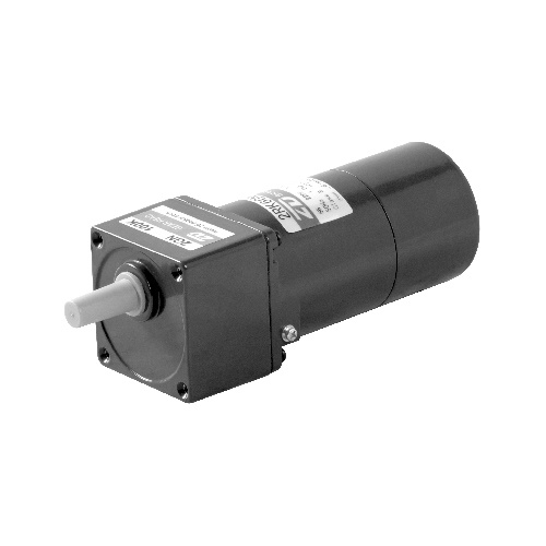
BRAKE MOTOR 60mm 6W
Min. Order (MOQ)
1 Piece
Lead Time
5-7Days
Ref. Price
Latest Price
Product Overview:
This type of motor does not contain a built-in simple brake mechanism.
Product Description
● This type of motor does not contain a built-in simple brake mechanism.
| Model · Type Lead Wire Type |
Rating | Output power W |
Voltage | Frequency Hz |
Current A |
Starting Torque mN.m |
Rated Torque mN.m |
Rated Speed r/min |
Capacitor μF |
||
| Pinion Shaft | Round Shaft | V | |||||||||
| 2RK6GN-AM | 2RK6A-AM | 30min | 6 | 1ph | 100 | 50 | 0.265 | 60 | 48 | 1200 | 4.0 |
| 60 | 0.232 | 55 | 40 | 1450 | |||||||
| 2RK6GN-EM | 2RK6A-EM | 30min | 6 | 1ph | 110 | 60 | 0.185 | 45 | 40 | 1450 | 2.5 |
| 1ph | 120 | 0.200 | |||||||||
| 2RK6GN-CM | 2RK6A-CM | 30min | 6 | 1ph | 220 | 50 | 0.145 | 55 | 48 | 1200 | 1.0 |
| 1ph | 230 | 0.150 | |||||||||
| 2RK6GN-HM | 2RK6A-HM | 30min | 6 | 1ph | 220 | 60 | 0.145 | 60 | 40 | 1450 | 1.0 |
| 1ph | 230 | 0.150 | |||||||||
| 2RK6GN-SM | 2RK6A-SM | 30min | 6 | 3ph | 220 | 50 | 0.076 | 85 | 48 | 1200 | - |
| 60 | 0.065 | 70 | 40 | 1450 | |||||||
| 2RK6GN-S3M | 2RK6A-S3M | 30min | 6 | 3ph | 380 | 50 | 0.044 | 85 | 48 | 1200 | - |
| 60 | 0.038 | 70 | 40 | 1450 | |||||||
● When the motor is approved under various safety standards, the model name on the nameplate is the approved model name.
●  :Contains a built-in thermal protector(automatic return). If a motor overheats for any reason, the thermal protector is opened and the motor stops.
● When the motor temperature drops, the thermal protector closes and the motor restarts. Be sure to turn the motor off before inspecting.
● Note: "-A" it means the voltage 110V, the assembly capacitor vaule it is according the labe.
■ Type
● Motor
| Type | Model | |
| Pinion Shaft | Round Shaft | |
| Lead Wire |
2RK6GN-AM | 2RK6A-AM |
| 2RK6GN-EM | 2RK6A-EM | |
| 2RK6GN-CM | 2RK6A-CM | |
| 2RK6GN-HM | 2RK6A-HM | |
| 2RK6GN-SM | 2RK6A-SM | |
| 2RK6GN-S3M | 2RK6A-S3M | |
● Parallel Shaft Gearhead (Sold Separately)
| Gearhead Type | Gearhead Model | Gear Ratio |
| Long Life ● Low Noise |
2GN□K | 3、3.6、5、6、7.5、9、10、 12.5、15、18、20、25、30、 36、40、50、60、75、90、 100、120、150、180、200 |
| 2GN10XK(Decimal Gearhead) | ||
■ Gear Motor-Torque Table
● Gearhead and mid-gearbox can be sold separately.
● Enter the gear ratio in the box (□) within the model name.
● The colored background  indicates the same rotating direction of the motor while the rotating direction of others are opposite.
● The speed is calculated by dividing the motor's synchronous speed (50Hz:1500r/min、60Hz:1800r/min) by the gear ratio. The actual speed is 2%~20% less than the displayed
value, depending on the size of the load.
● To reduce the speed beyond the gear ratio in the table, attach a decimal gearhead (gear ratio:10) between the gearhead and motor. In that case, the permissible torque is 3N·m.
■ Allowance Torque Unit: Upside(N.m)/ Belowside(kgf.cm)
| Type Motor/Gearhead |
Gear Ratio | 3 | 3.6 | 5 | 6 | 7.5 | 9 | 10 | 12.5 | 15 | 18 | 20 | 25 | 30 | 36 | 40 | 50 | 60 | 75 | 90 | 100 | 120 | 150 | 180 | 200 | |
| Speed r/min | 50Hz | 500 | 417 | 300 | 250 | 200 | 166 | 150 | 120 | 100 | 83 | 75 | 60 | 50 | 41 | 37 | 30 | 25 | 20 | 16 | 15 | 12.5 | 10 | 8.3 | 7.5 | |
| 60Hz | 600 | 500 | 360 | 300 | 240 | 200 | 180 | 144 | 120 | 100 | 90 | 72 | 60 | 50 | 45 | 36 | 30 | 24 | 20 | 18 | 15 | 12 | 10 | 9 | ||
| 2RK6GN-AM 2RK6GN-EM 2RK6GN-CM 2RK6GN-HM 2RK6GN-SM 2RK6GN-S3M |
2GN□K | 50Hz | 0.12 | 0.14 | 0.19 | 0.23 | 0.29 | 0.35 | 0.39 | 0.49 | 0.58 | 0.70 | 0.75 | 0.88 | 1.10 | 1.30 | 1.39 | 1.60 | 1.90 | 2.40 | 2.90 | 3.00 | 3.00 | 3.00 | 3.00 | 3.00 |
| 1.22 | 1.43 | 1.94 | 2.35 | 2.96 | 3.57 | 3.98 | 5.00 | 5.92 | 7.14 | 7.65 | 8.98 | 11.2 | 13.3 | 14.2 | 16.3 | 19.4 | 24.5 | 29.6 | 30.0 | 30.0 | 30.0 | 30.0 | 30.0 | |||
| 60Hz | 0.10 | 0.12 | 0.16 | 0.19 | 0.24 | 0.29 | 0.32 | 0.41 | 0.49 | 0.58 | 0.62 | 0.73 | 0.88 | 1.10 | 1.15 | 1.30 | 1.60 | 2.00 | 2.40 | 2.60 | 3.00 | 3.00 | 3.00 | 3.00 | ||
| 1.02 | 1.22 | 1.63 | 1.94 | 2.45 | 2.96 | 3.26 | 4.18 | 5.00 | 5.92 | 6.32 | 7.45 | 8.98 | 11.2 | 11.7 | 13.3 | 16.3 | 20.4 | 24.5 | 26.5 | 30.0 | 30.0 | 30.0 | 30.0 | |||
■ To Allow The Hoisting Of The Load Allow Axial Load
Motor (Round shaft) →P215
Gearhead→P215
■ Permissible Load Inertia J For Gearhead
P215
■ Starting And Brake Characteristics (Reference Values)


■ Dimensions (Unit mm)
Mounting screws are included with gearhead.
● Lead Wiring Type
Weight:Motor:1.1kg Gearhead: 0.4kg

| Motor Model | Gearhead Model | Gear Ratio | L1 |
| 2RK6GN-AM 2RK6GN-EM 2RK6GN-CM 2RK6GN-HM 2RK6GN-SM 2RK6GN-S3M |
2GN□K | 3~200 | 41.5 |
● Gear ratio 3~18, short case is possible (L1=32)
Excluding weight and the shaft section motor shape are the same as those of the pinion shaft type.
Can be connected to GN pinion shaft type
3GN10XK
Weight :0.3kg
■ Formal Dimension Of Capacitor
| Model | Capacitor Model | L | W | H | |
| Pinion Shaft | Round Shaft | ||||
| 2RK6GN-AM | 2RK6A-AM | ZD40CFAUL | 47 | 17 | 31 |
| 2RK6GN-EM | 2RK6A-EM | ZD25CFAUL | 38 | 17 | 28 |
| 2RK6GN-CM | 2RK6A-CM | ZD10BFAUL | 36 | 11 | 22 |
● Enter the code that represents the terminal box type (T) in the box (□) within the model name

■ Wiring Diagram
● The direction of motor rotation is as viewed from the shaft end of motor. CW represents the clockwise direction, while CCW represents the counterclockwise direction.
● Name indicated in the list is pinion shaft type, also valid for the equivalent round shaft type.
| Single-phase Motor |
| 2RK6GN-AM、2RK6GN-EM、2RK6GN-CM、2RK6GN-HM |
Sw1 operates both motor and electromagnetic brake action. (Switched simultaneously)
The motor will rotate when SW1 is switched simultaneously to ON.
When SW1 is switched simultaneously to OFF, the motor stops immediately with the electromagnetic brake and holds the load.
If you wish to release the brake while the motor is stopped, set the SW1 to off and connection point at the side of black lead to ON.
Direction of Rotation.
To rotate the motor in a clockwise (CW) direction, turn SW2 to CW.
To rotate the motor in a counterclockwise (CCW) direction, turn SW2 to CCW.

| Switch No. |
Capacitor of Switch Connection Point | Note | |
| Single-Phase 100V, 110/120V Input |
Single-Phase 220V, 230V Input |
||
| SW1 | AC 125V 3A minimum (Inductive Load) |
AC 250V 1.5A minimum (Inductive Load) |
Switched Simultaneously |
| SW2 | - | ||
|
Three-phase Motor |
|
2IK6GN-SM(S3M) |
SW1 operates both motor and electromagnetic brake action. (Switched Simultaneously)
The motor will rotate when SW1 is switched simultaneously to ON.
When SW1 is switched simultaneously to OFF, the motor stops immediately with the electromagnetic brake and holds the load.
If you wish to release the brake while the motor is stopped, set the SW1 to off and connection point at the side of black lead to ON.
Direction of Rotation.
To change the rotation direction, change any two connections between R, S and T.

| Switch No. |
Capacitor of Switch Connection Point | Note | |
| Single-Phase 100V, 110/120V Input |
Single-Phase 220V, 230V Input |
||
| SW1 | AC 125V 3A minimum (Inductive Load) |
AC 250V 1.5A minimum (Inductive Load) |
Switched Simultaneously |
| SW2 | |||
Notes:
● R0C0 indicate surge suppressor circuit. [R0=5~200Ω, C0=0.1~0.2μF, 200WV (400WV) ] EPCR1201-2 is available as an optional surge suppressor.
