

CSF Standard Cup Type
Min. Order (MOQ)
10
Lead Time
5-7
Ref. Price
Latest Price
Product Overview:
CSF Standard Cup Type
Product Description
■ CSF Series
The strain wave reducer of CSF series have a standard cup-shaped flexspline, the input shaft is matched with the inner hole of wave generator through Oldham’s coupling which has a function of certain self-alignment.
● Rated Parameters
| Model | Reduction ratio |
Rated torque @2000 r/min (Nm) |
Permissible peak torque of starting/stopping (N ·m) |
Permissible max value of ave. load torque (N ·m) |
Instantaneous permissible max torque (N ·m) |
Permissible max input rotational speed (r/min) |
Permissible ave input rotational speed (r/min) |
Inertia moment (×10*kgm²) |
Life in design (h) |
| 14 | 50 | 5.4 | 18 | 6.9 | 35 | 8500 | 3500 | 0.033 | 10000 |
| 80 | 7.8 | 23 | 11 | 47 | |||||
| 100 | 7.8 | 28 | 11 | 54 | |||||
| 17 | 50 | 16 | 34 | 26 | 70 | 7300 | 3500 | 0.079 | 10000 |
| 80 | 22 | 43 | 27 | 87 | |||||
| 100 | 24 | 54 | 39 | 108 | |||||
| 20 | 50 | 25 | 56 | 34 | 98 | 6500 | 3500 | 0.193 | 10000 |
| 80 | 34 | 74 | 47 | 127 | |||||
| 100 | 40 | 82 | 49 | 147 | |||||
| 120 | 40 | 87 | 49 | 147 | |||||
| 25 | 50 | 39 | 98 | 55 | 186 | 5600 | 3500 | 0.413 | 10000 |
| 80 | 63 | 137 | 87 | 255 | |||||
| 100 | 67 | 157 | 108 | 284 | |||||
| 120 | 67 | 167 | 108 | 304 | |||||
| 32 | 50 | 76 | 216 | 108 | 382 | 4800 | 3500 | 1.690 | 10000 |
| 80 | 118 | 304 | 167 | 568 | |||||
| 100 | 137 | 333 | 216 | 647 | |||||
| 120 | 137 | 353 | 216 | 686 |
● Transmission accuracy
unite: arc-min
| Reduction ratio | Model | 14 | 17 | 20 | 25 | 32 |
| 50 | 1.8 | 1.8 | 1.5 | 1.5 | 1.5 | |
| 80 or more | 1.5 | 1.5 | 1.2 | 1.2 | 1.2 | |
● Lost motion
unite: arc-min
| Reduction ratio | Model | 14 | 17 | 20 | 25 | 32 |
| 50 | 2.0 | 2.0 | 2.0 | 2.0 | 2.0 | |
| 80以上80 or more | 1.0 | 1.0 | 1.0 | 1.0 | 1.0 | |
● Max. backlash quantity
Unit: arc-sec
| Reduction ratio | Model | 14 | 17 | 20 | 25 | 32 |
| 50 | 60 | 60 | 36 | 36 | 36 | |
| 80 | 40 | 40 | 32 | 32 | 32 | |
| 100 | 35 | 35 | 35 | 30 | 30 | |
| 120 | - | - | - | 28 | 28 | |
● Torsional rigidity
| Symbol | Model | 14 | 17 | 20 | 25 | 32 |
| T₁ | N-m | 2.00 | 3.90 | 7.00 | 14.0 | 29.0 |
| T₂ | N ·m | 6.90 | 12.0 | 25.0 | 48.0 | 108 |
| Reduction ratio 50 | K,(×10⁴N-m/rad) | 0.34 | 0.81 | 1.30 | 2.50 | 5.40 |
| K₂ (×10'N ·m/rad) | 0.47 | 1.10 | 1.80 | 3.40 | 7.80 | |
| K₃ (×10⁴N ·m/rad) | 0.57 | 1.30 | 2.30 | 4.40 | 9.80 | |
| θ,(arc min) | 2.00 | 1.70 | 1.80 | 1.90 | 1.90 | |
| θ₂ (arc min) | 5.60 | 4.20 | 5.30 | 5.40 | 5.40 | |
| Reduction ratio 80 or more |
K,(×10*N ·m/rad) | 0.47 | 1.00 | 1.60 | 3.10 | 6.70 |
| K₂ (×10°N ·m/rad) | 0.61 | 1.40 | 2.50 | 5.00 | 11.0 | |
| K₃ (×10*N-m/rad) | 0.71 | 1.60 | 2.90 | 5.70 | 12.0 | |
| θ,(arc min) | 1.40 | 1.30 | 1.50 | 1.50 | 1.50 | |
| θ₂ (arc min) | 4.20 | 3.30 | 3.90 | 3.80 | 4.00 |
■ Outline drawing
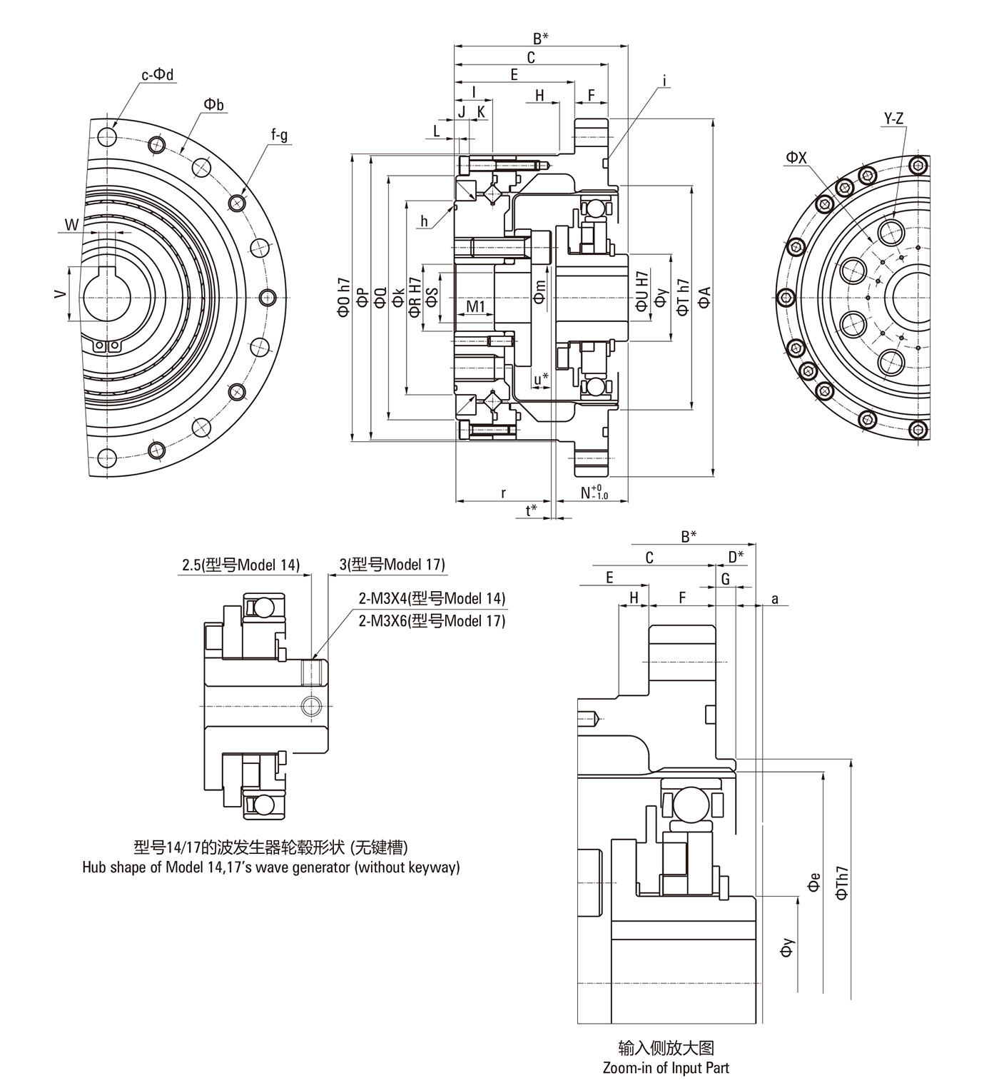
Note: The engagement length of bolt should be less than the depth of internal thread. ΦS represent the shape of the through hole which leads to the inside of the product. The shape
of the output flange will be different according to different models of reducers. For details of dimensions, please confirm the delivered outline drawing with reducer.
■ Specification Table
| Symbol | Model | 14 | 17 | 20 | 25 | 32 |
| ΦA | 73 | 79 | 93 | 107 | 138 | |
| B* | 41+0- 0.9 | 45+0- 0.9 | 45+0- 1.0 | 52+0- 1.0 | 62+0- 1.1 | |
| C | 34 | 37 | 38 | 46 | 57 | |
| D* | CSG | 7+0- 0.4 | 8+0- 0.4 | 7.5+0- 0.4 | 6+0- 0.5 | 5+0- 0.5 |
| CSF | 7+0- 0.8 | 8+0- 0.9 | 7.5+0- 1.0 | 6+0- 1.0 | 5+0- 1.1 | |
| E | 27 | 29 | 28 | 36 | 46 | |
| F | 7 | 8 | 10 | 10 | 12 | |
| G | 2 | 2 | 3 | 3 | 3 | |
| H | 3.5 | 4 | 5 | 5 | 5 | |
| 1 | 16.5 | 16.5 | 16.5 | 18.5 | 22.5 | |
| J | 4.5 | 4.5 | 4 | 4.5 | 5.5 | |
| K | 12 | 12 | 12.5 | 14 | 17 | |
| L | 0.5 | 0.5 | 0.5 | 0.5 | 1.0 | |
| M1 | 9.4 | 9.5 | 9 | 12 | 15 | |
| N+0- 0.1 | CSG | 18.5 | 20.7 | 21.5 | 21.5 | 23.6 |
| CSF | 17.6 | 19.5 | 20.1 | 20.2 | 22 | |
| Ф0h7 | 56 | 63 | 72 | 86 | 113 | |
| ФP | 55 | 62 | 70 | 85 | 112 | |
| ФQ | 42.5 | 49.5 | 58 | 73 | 96 | |
| ΦR1 H7 | 11 | 10 | 14 | 20 | 26 | |
| ФS | 8 | 7 | 10 | 15 | 20 | |
| ФT h7 | 38 | 48 | 56 | 67 | 90 | |
| ФU h7 | 6 | 8 | 12 | 14 | 14 | |
| V | - | 9.4+0.1+0 | 13.8+0.1+0 | 16.3+0.1+0 | 16 .3+0.1+0 | |
| W Js9 | - | 3 | 4 | 5 | 5 | |
| ФX | 23 | 27 | 32 | 42 | 55 | |
| Y | 6 | 6 | 8 | 8 | 8 | |
| Z | M4X8 | M5X10 | M6X9 | M8X12 | M10X15 | |
| a | 1 | 1 | 1.5 | 1.5 | 1.5 | |
| Φb | 65 | 71 | 82 | 96 | 125 | |
| C | CSG | 8 | 8 | 8 | 10 | 12 |
| CSF | 6 | 6 | 6 | 8 | 12 | |
| Φd | 4.5 | 4.5 | 5.5 | 5.5 | 6.6 | |
| Φe | 38 | 45 | 53 | 66 | 86 | |
| f | CSG | 8 | 8 | 8 | 10 | 12 |
| CSF | 6 | 6 | 6 | 8 | 12 | |
| g | M4 | M4 | M5 | M5 | M6 | |
| h | 29X0.5 | 34.5X0.8 | 40.64X1.14 | 53.28X0.99 | S71:70.5X2 | |
| i | 48X2 | 53X2 | 66X2 | 78X2 | 102X2 | |
| Φk | 31 | 38 | 45 | 58 | 78 | |
| Φm | 10 | 10.5 | 15.5 | 20 | 27 | |
| 21.4 | 23.5 | 23 | 29 | 37 | ||
| t* | CSG | 1.1 | 0.8 | 1 | 1.4 | 1.4 |
| CSF | 2 | 2 | 2.4 | 2.8 | 3 | |
| u* | CSG | 5.1 | 5.8 | 6 | 7.4 | 9.4 |
| CSF | 6 | 7 | 7.4 | 8.8 | 11 | |
| Φy | 14 | 18 | 21 | 26 | 26 | |
| Weight(kg) | 0.52 | 0.68 | 0.98 | 1.5 | 3.2 | |
| · Specification with * mark: The B, D, t, u indicate the mounting positions in the shaft direction and allowance of the three parts--wave generator, flexspline, circular spline. Strictly follow the requirement of these specifications as they affect the performance and intensity. |
||||||
| · The dimension tolerances are existing according to different manufacturing methods. | ||||||
| · The wave generator is packed separately when the product is delivered. | ||||||
